Rapid Control Prototyping
Rapid control prototyping applications
View application
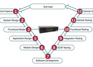 One of the key benefits of RCP is the ability to prove out a control algorithm early in the design process. No software coding is necessary – using a model-based design approach, engineers can quickly create the model graphically using Simulink, or state diagram using Stateflow, and build and executable directly from the host PC. In minutes the algorithm can be tested in real hardware.
Communications gateway applications
View application

Communications gateways are efficient solutions for exchanging information over two or more communications buses when required.
A typical application of communications gateways is when the contents of a particular communications bus needs to be adapted for reasons of compatibility to allow error free communications; such as when new electronics controllers are introduced to an existing system.
Model-based design using Simulink
View application
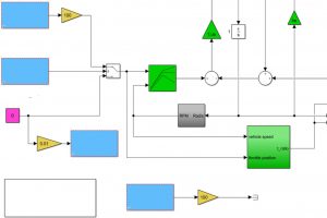
Using a model-based design for embedded control systems, simulation and test systems allows you to test earlier and control the entire design process more closely.
By detailing the hardware requirements as well as the control or plant requirements, the entire system can be ‘built’ and tested in the lab.
Industry standard Simulink® from TheMathworks brings quality and stability, along with a desktop environment that is designed to save you time during the development and testing of your products.
‘Rest-bus’ Simulation
View application
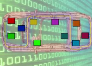
Rest-bus Simulation is a technique that can be employed when testing devices on communication networks where the ‘rest of the bus’ is simulated in order to facilitate testing the controller in question.
It usually entails simulating more than one ECU bus connection or node. Sometimes an entire network’s ECUs need to be simulated to represent the communications bus load and provide the appropriate signals to test the ECUs’ functionality.
Complex user interface design for aerospace systems
View application
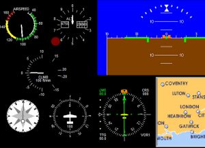
Aerospace applications often call for complex user interfaces due to the potentially huge Simulink® models that can be deployed in the FADECs.
This calls for a graphical user interface design tool capable of a massive number of connections to the real-time system and one that is able to display many more user controls than traditional tools have been capable of in the past.