Read how add2 helped Ford to further strengthen its verification & validation testing processes, introducing simulation technologies earlier to shorten the development cycle, increase its value and reduce its cost. This was achieved through holistic redesign of a common automotive test environment, combined with custom closed-loop simulation of dynamic vehicle signalling.
The problem
Historically, much vehicle embedded systems testing has been conducted using prototype vehicles; either on test tracks or the open road. Whilst representative of real-world driving scenarios, this approach made execution of precise, repetitive or unsafe test procedures difficult.
For example, fuel indication accuracy testing was performed through the driving of instrumented vehicles on public roads until failure; a test that took around eight hours per vehicle configuration. Similarly, wheel speed signal accuracy was tested using prototype vehicles on private test tracks, taking around four days per vehicle model year to complete.
The DTB is mounted on the test board, and can utilise an external lab supply if required.
A significant proportion of electrical and electronics testing for passenger cars, trucks and commercial vehicles is conducted using test boards. These are substitutes for prototype vehicles, and consist of all production-intent electrical components for a vehicle model year, connected together in the lab using the vehicle harness.
This setup is used to verify a wide range of functionality, from simple functionality tests to more advanced communications bus analysis. However, to date it has been a less than ideal setup, as signals associated with vehicle movement, including many dynamic parts, engine speeds, moving fuel and so on – upon which controllers increasingly rely – were entirely absent.
Therefore, tests that were non-feasible in this environment were suitable only to be performed using prototypes or hardware-in-the-loop testing – at significant cost.
Interested? Contact us to learn more
The solution
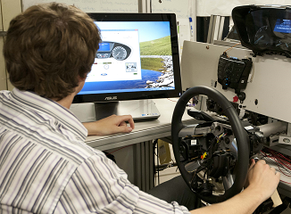
Control of the DTB is via GUI, scripting or production-intent components.
To meet this challenge, the driveable test board was developed, improving the representativeness of the test board environment. This would, in turn, allow for a higher standard of testing, both against the build specification, and passenger expectations.
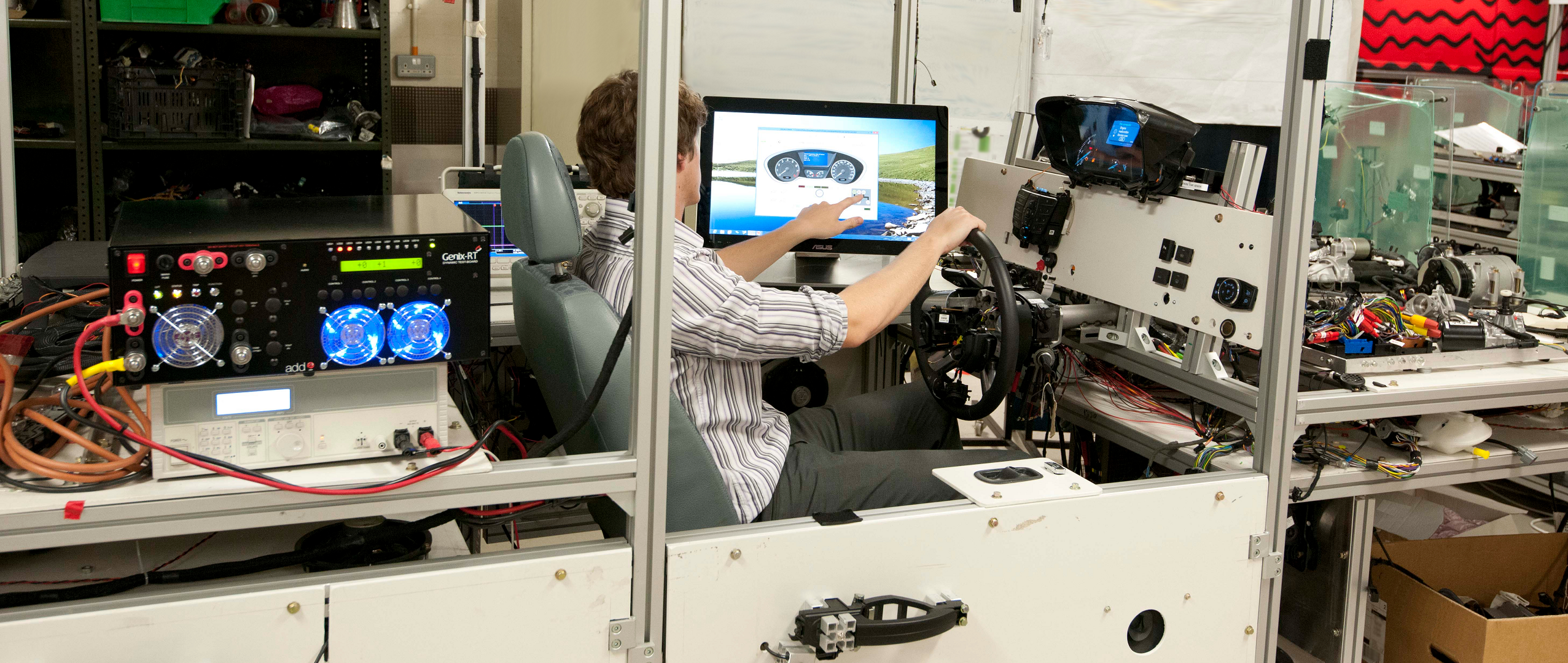
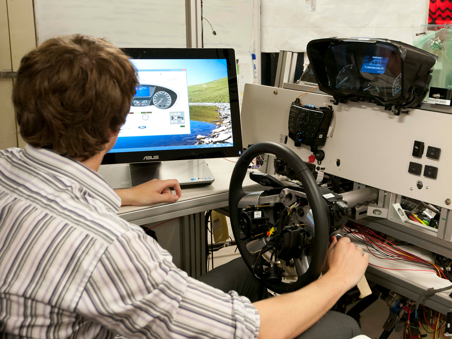
The first step was to improve the configuration of the testing environment itself. A driver’s seat was installed, the instrument cluster was positioned at eye level relative to this seating position – the test board was even fitted with functioning doors.
All other vehicle electronic components were positioned roughly equivalent to the target vehicle, attached to a custom frame built for the purpose. This revised physical setup alone was sufficient to improve test procedures, as more representative system operation allows for validation of how the system works under normal driving behaviour.
The second step was to introduce closed-loop simulation of dynamic vehicle signals with behaviours linked together, specifically:
- Engine simulation, inclusive of crankshaft speed, camshaft speed, temperature, fuel rail pressure
- Transmission simulation, including gear ratios and gear position signals
- Vehicle dynamics, such as vehicle and wheels speeds
- Vehicle power supply voltage perturbation, due to cranking and other common phenomena
The simulator hardware connects to both a host PC, and auxiliary equipment produced by add2. This equipment has several functions, for example the stimulation of wheel speed sensors to calculate vehicle speed, and the detection of fuel injector pulses for closed-loop torque estimation.
 “The financial value of the driveable test-board can be estimated to be one to two orders of magnitude greater than the purchase and operation cost”
Kyaw Soe, Electronics Systems & Verification Engineer, Ford Motor Company.
Ref: Soe, K., “Driveable Automotive Electrical & Electronics Test-Board,” SAE Technical Paper 2017-01-1681, 2017.
The simulator itself contains a MICROGen reprogrammable control module capable of running the powertrain plant model, controlling the I/O and interfacing with the host PC. It has over 100 automotive I/O built in, whose signal conditioning can be re-configured in software, and comes pre-configured for 5V and 12V systems.
Four H3 intelligent I/O modules contained within a DIN rail mountable sub-assembly provide angle-based signals, simulating the sensors that locate crankshaft and camshaft positions within the engine. This separate unit provides the signals necessary to simulate engine speed, and reduces the load on MICROGen target system.
The LVTGO vehicle power supply perturbation simulation system can condition up to 3kW of power sourced from an internal or external power supply. It delivers voltage waveforms covering EMC standards such as ISO 16750, CI 260 and CI 265, allowing the compliance of systems to be established, and through randomisation of these waveforms enhanced component robustness.
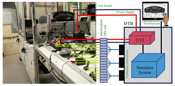
Diagram showing the connection of the DTB system to the test board, and the host PC.
The touchscreen GUI developed for the simulator was produced using add2’s VISUALCONNX real-time interface creation suite. It allows vehicle configurations to be selected and customised, and through class libraries enables functional changes to be made easily and quickly.
The powertrain simulation model was designed for simplicity, and has a level of complexity appropriate to the application, consisting of several physical functions, lookup tables and approximations connected together. The central powertrain model operates independently, with simulation of crankshaft and camshaft speeds taking place via high-speed intelligent I/O modules.
The completed drivable test board system was tested in several phases. Firstly, the testboard design was validated during a commercial vehicle development programme. Next, parallel testing was performed of the hardware and simulation model. Features were then added in an iterative process throughout the integration, commission and piloting phases.
Impact

The DTB helps to cut down on expensive prototype testing hours on the test track or open road.
The DTB allows the scope and coverage of testing to be extended compared to a traditional testboard. This allows tests to be moved from both hardware-in-the-loop facilities and prototype vehicles; both of which are in high demand, and expensive.
The complete driveable test board system can be constructed for around 25-40% of the cost of a prototype vehicle, which of course cannot be reused as this system can. A full vehicle hardware-in-the-loop system costs a full order of magnitude more than this system.
It allows a significant proportion of testing to take place earlier, and allows engineers to start testing after around a month’s commissioning time and an hour’s training per engineer. This figure can be around six months for a fully-functional HIL system.
Where previously fuel indication accuracy testing was a manual process taking eight hours per vehicle configuration, thanks to the DTB only one physical drive needs to take place, saving on the cost of all other drives. Wheel speed accuracy testing has been reduced from four days on the test track to a single test taking under an hour.
In conclusion, this setup has led to a multi-dimensional increase in the scope and coverage of testing, compared to traditional test boards. Testing has been simplified through the integration of equipment through a central GUI. The systems extensible I/O and broad functionality including voltage perturbation testing and extensible I/O make testing more flexible than before. This allows for consequential savings on prototype vehicle costs and allows more representative and complex testing to take place on the test board.
From a financial perspective, value of the driveable test-board can be estimated to be one to two orders of magnitude greater than the purchase and operation cost.
